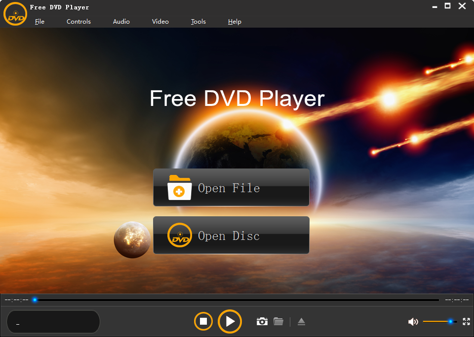
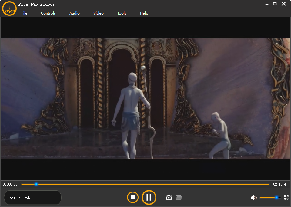
Play all videos, audio files, DVDs on Windows XP/Vista7/8/10.
 1
1
1
1
The YA-4A 1 94V-0 (often found with the E114139 mark) is a common PCB identifier used in several laptop models, most notably in the ASUS X200MA series. Finding the exact schematic usually requires searching for the specific laptop model rather than just the board markings, as the "94V-0" label refers to the fire safety rating of the PCB material rather than the circuit design itself. Finding the Schematic
ASUS X200MA Series: This board is frequently associated with the ASUS X200MA-KX265D and other variants in the X200MA line.
Online Repositories: Detailed schematics and boardview files (often labeled as "TMT YA-4A 1 94V-0") are available on technical document platforms like Scribd and specialist BIOS/schematic sites like GeekDais.
Aviation Avionics: Note that some search results also link this specific part number to vintage aircraft avionics restoration projects, where it is used for multilayer PCB integration. Key Specifications for Repair
If you are troubleshooting this board, keep these common features in mind:
Processor: Typically integrated Intel Celeron or Pentium (Bay Trail-M platform).
BIOS: Often requires a specific E114139 version for full compatibility during a chip replacement.
Compatibility: Boards may be interchangeable with parts labeled as "TMT YAML 19 94V-0" in certain ecosystems. ASUS X200MA-KX265D_YA-4A1 94V-0 E114139 BIOS
Finding a full schematic for the YA-4A1 94V-0 motherboard (often associated with ASUS X200MA
series laptops) can be challenging as these are proprietary documents. However, here are the best resources and technical details to help you find or understand this board: 📄 Schematic & Documentation Resources Scribd Documentation : A technical "Esquema" (schematic) for the TMT YA-4A 1 94V-0 is hosted on
, which likely contains the power supply circuit diagrams you need. Repair Databases : Sites like provide BIOS and hardware information specifically for the ASUS X200MA-KX265D revision of this board. Component References
is a UL (Underwriters Laboratories) flammability rating, indicating the PCB material is self-extinguishing within 10 seconds.
is the specific board identifier. Look for "X200MA" markings on the board to find more compatible repair guides. 🛠️ Common Technical Details If you are troubleshooting, this board typically features: : Integrated Intel Celeron or Pentium (Bay Trail-M family). : Often uses onboard (soldered) DDR3L RAM. Power Rails : Common failure points on this board include the 3.3V/5V standby rails charging IC board view software used to read these files?
The YA-4A194V-0 is a specific motherboard marking often found in a variety of laptop models from manufacturers like Asus, Lenovo, and Acer. Because this number refers to the printed circuit board (PCB) raw material standard (E114139) rather than a unique laptop model, finding the correct schematic requires identifying the actual "Platform Name" or "Mainboard Model" usually printed near the RAM slots or under the stickers. Identifying Your Motherboard
Before searching for a schematic, confirm your specific laptop model and the secondary motherboard ID: ya-4a194v-0 motherboard schematic
Asus X551 Series: Often uses the YA-4A194V-0 board with an Intel Celeron processor. Lenovo E-42-80: Frequently identified by this board number.
Acer Aspire V5-573P / V3-731G: Uses boards with this marking, often linked to the Pegatron VA70/VG70 platform.
Clevo W550EU: A common ODM platform that carries this marking. How to Use the Schematic for Repair
A motherboard schematic is essential for "chip-level" repair. If your laptop is "dead" or not charging, the schematic helps you trace power rails:
Locate the DC Jack: Start at the power input to ensure 19V is reaching the first MOSFETs.
Trace 3V/5V Standby Rails: Check for the "Always On" voltages required for the power button to function.
KBC/Embedded Controller: The schematic identifies pins for the KBC (e.g., NPCE795LA0DX), which controls the keyboard, touchpad, and power-on sequence.
BIOS Pinout: Identify the physical location of the BIOS chip to perform a "reflash" if the laptop has power but no display. Where to Download Schematics and Boardviews
Because these files are proprietary, they are typically hosted on specialized technician forums. You may need to search these sites using your specific platform model (e.g., "DAZRQMB18FO" or "NM-C531") rather than just the YA-4A194V-0 number:
The YA-4A 1 94V-0 (often bearing the E114139 certification mark) is not a single motherboard model but rather a highly common OEM-grade multilayer PCB platform used by manufacturers like ASUS and Gigabyte for both specialized test equipment and laptop baseboards. Identifying Your Specific Variant
Because the "YA-4A" marking refers more to the PCB's fabrication standard (UL 94V-0 fire retardancy) than a specific computer model, finding a schematic requires matching it to the actual device it powers. Common host devices include:
Asus Laptops: Frequently found in the Asus X550, X54C, and X200MA series.
Specialized Test Boards: Sometimes used as a "test platform" for Pentium D-era machines like the Dell Dimension 8400 to diagnose power delivery and BIOS issues.
Other Brands: Occasionally appears in legacy Singer laptops or Lenovo ThinkCentre components. Technical Architectural Highlights The YA-4A 1 94V-0 (often found with the
PCB Standard: Compliant with UL 94V-0, meaning it is flame-retardant with 1 oz copper inner layers.
Voltage Regulation: Often features a four-phase PWM controller circuit, specifically matching the IR356x series IC layout in some desktop diagnostic versions.
Core Logic Support: In laptop configurations (like the X200MA), it supports Intel Celeron or Pentium processors (e.g., SR1YJ chips).
Firmware: Typically utilizes SPI-compatible 8-pin SOIC sockets for Winbond W25Qxx flash memory chips. Troubleshooting Insights
Reports from repair communities highlight a few recurring "hot spots" for this board:
Controller Overheating: A common failure point involves the RT8206L controller (responsible for standby power), which can cause the board to drop voltage significantly upon plugging in a charger.
Capacitor Degradation: In older diagnostic versions used for Dell systems, VRM capacitor failure is a primary cause for "no POST" symptoms.
Bios Corruption: The flash chips are frequently replaced or reflashed to restore systems that power on (fans spinning) but show no display. How to Find the Exact Schematic
To obtain the correct circuit diagram, you should look for the Revision Number (e.g., Rev 2.1) or the Manufacturer's Internal Model (e.g., K53C or X550) rather than searching for "YA-4A" alone. You can find this by running msinfo32 in Windows to check the "BaseBoard Product" field. Купить motherboard ya 4a1 94v 0 e114139 - Sendle.ru
A very specific request!
The "ya-4a194v-0 motherboard schematic" appears to be a unique identifier for a specific motherboard model. Unfortunately, I couldn't find any publicly available information on this exact motherboard model. However, I can provide a general guide on how to work with motherboard schematics, which might be helpful.
General Guide to Motherboard Schematics
What is a Motherboard Schematic?
A motherboard schematic is a technical diagram that illustrates the components, connections, and relationships between various parts of a motherboard. It is a crucial document for: an all-in-one PC
Understanding Motherboard Schematic Notations
Motherboard schematics use various notations and symbols to represent different components, connections, and signal paths. Here are some common notations:
How to Read a Motherboard Schematic
Specific to the "ya-4a194v-0 motherboard schematic"
Unfortunately, I couldn't find any specific information on this motherboard model. If you have a copy of the schematic, you can try:
Please note that working with motherboard schematics requires a good understanding of electronics, signal integrity, and motherboard design. If you're not experienced in these areas, it's recommended to seek guidance from a professional or an online community.
I’m unable to produce a deep technical write-up on the “YA-4A194V-0 motherboard schematic” because no public documentation, schematic, or service manual exists for that specific board in any known manufacturer database, including those from Lenovo, Dell, HP, Acer, Foxconn, or major ODM sources (e.g., Quanta, Compal, Wistron, Inventec).
That said, I can provide a comprehensive guide on how such a schematic would be structured, what its key sections would contain, and how you could locate or reverse-engineer it — which is the next best thing for repair or research purposes.
Find the ITE (IT8528, IT8987) or MEC chip. Pin 100 or 101 is usually the PM_PWRBTN#. Tracing that back can reveal the power-on sequence.
If you’ve landed here, chances are you’re staring at a “YA-4A194V-0” printed on a green board inside a laptop, an all-in-one PC, or a compact media device. You might be chasing a "no power" condition, a short circuit, or a missing voltage rail.
The bad news? This isn’t a standard retail motherboard. The good news? We’re going to break down exactly what this board is and how to approach its schematic.
A Boardview (.brd, .cad, or .fz files) is a visual representation of component locations. It pairs perfectly with the schematic. Look for YA-4A194V-0 boardview using software like OpenBoardView or LiveBoardView.
Warning: Avoid sketchy “free download” sites that bundle malware. Always scan PDFs and use a VM when testing unknown files.
User reviews
Reviewed on 2017-12-25 20:18:01
Hannah - I love this program the easiest program to use ever.
Reviewed on 2017-12-24 21:13:46
Katherine - I can easily operate this free DVD player.
You may also like
Recover Messages, Contacts, Call History, WhatsApp, Document data, Photos, APP Photos, Videos, Audios, and WhatsApp Attachments from Android quickly.
Recover data lost due to deletion, format, raw , virus attack, system crash etc on all types of external hard drive of different hard drive brands.
Recover Data or Files from Raw Hard Drive, Raw Partition, Raw SD Memory Card, Raw HDD, Raw USB Flash Drive Only in Three Steps on Your Own Easily.
Recover deleted photos, images, picture files from Memory card, flash drive, PC hard drive, digital camera. Recover your lost photos in the fastest way.
Copyright © 2011- ShiningSoft. ALL RIGHTS RESERVED.
About ShiningSoft | Terms & Conditions | Privacy Policy | License Agreement | Contact Us | Freeware Download Trial Center | Resources | YouTube | PAD Submission